We’re going to be taking a look at a (transmit-only) UART implementation in pure assembly language. We will use this as an example to walk through some basics of the ARM instruction set, and also to show some concepts of the architecture.
My initial motivation for this was to establish some understanding of the instruction set, just enough to make sense of asm snippets you come across occasionally in Embedded.
Let’s get started!
Table of Contents
- Hardware
- Build System
- Hello World: Driving an output as fast as we can!
- A little refactoring: Extracting Subroutines
- Outputting a proper serial frame
- Summary, References
Hardware
We will use a Raspberry Pi Zero v1.3 for these examples. It is a pretty cheap device that comes with a Broadcom SoC which employs an ARM11 32-bit RISC processor. Unfortunately, at the time of writing (Aug-2022) even this device is hard to get, just like all Raspberry Pis.
I will also say this device is rather awkward when it comes to loading and debugging code: the GPU has control over the processor, and accessing the JTAG port of the processor is complicated (if at all possible; I haven’t tried it myself). That said, there’s a serial bootloader I found on github that makes loading code convenient enough.
Here are the steps needed to get the basic setup up and running. Feel free to skip the rest of this section in case you are more interested in looking at code than running on actual hardware.
Initial Setup Steps
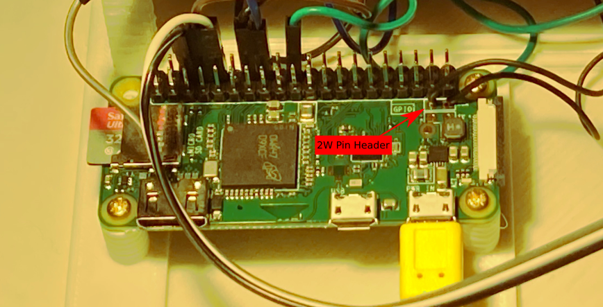
- Add a reset button to the board (see photo below)
- Hook up a USB-UART converter
- Prepare SD card firmware
- Install an OS (e.g. Raspberry Pi OS)
- or download firmware files from here (bootcode.bin and start.elf) and place them in the root directory of the SD card.
- Prepare serial bootloader (bootloader.img by David Welch)
- You can either build it from source (see instructions)
- or download a pre-built binary from here.
- Copy bootloader.img to the root directory of the SD card. Make sure to rename it to kernel.img so it is recognized by the Pi.
- Launch a serial terminal with the board connected.
sudo picocom /dev/ttyUSB0 -b 115200 - Reset the board. You should see the following bootloader message appear on the terminal while the LED is flashing twice.
12345678 002002B8 SREC- Press
Ctrl-a-xto exit picocom.
- Press
- Transfer an example program onto the board
- Download the pre-compiled program from here: notmain.srec
- This file contains an ASCII representation of the machine code (in SREC format) so you can write it to the serial port as-is:
cat nomain.srec > /dev/ttyUSB0
- Run the program
- After transferring the file, the bootloader waits for a command to start executing.
echo "g" > /dev/ttyUSB0 - The LED should blink now.
- Note: you need to run the terminal program at least once (or use stty as an alternative), to set terminal parameters like baud rate. In case piping to /dev/ttyUSB0 won’t work, consider checking file permissions and/or try running as root.
- After transferring the file, the bootloader waits for a command to start executing.
These are the things you need to load and run any program. You will notice the bootloader won’t store the program persistently; we need to re-load it after every power cycle.
The following image shows where to connect the reset button (2W PIN HEADER, according to the schematics).
Build System
Now that we are able to load pre-compiled binaries to our board, let’s figure out how to create these ourselves. Note the following ideas are all based on a template provided by Alex Chadwick (University of Cambridge). In summary, these are the steps that need to happen:
- Run assembler to create an object file from assembly code.
- Run linker to create elf from object file(s).
- Convert elf to srec format using objcopy.
A simple Makefile as shown in the following snippet works fine for this purpose. Please note for this to work you’ll want to make sure you’ve got the expected cross-toolchain installed on your system. On Ubuntu, that means running sudo apt-get install gcc-arm-none-eabi.
# Makefile

TARGET = swuart

$(TARGET).o: $(TARGET).s
	arm-none-eabi-as $< -o $@

$(TARGET).elf: $(TARGET).o
	arm-none-eabi-ld $< -o $@ --script kernel.ld

$(TARGET).srec: $(TARGET).elf
	arm-none-eabi-objcopy --srec-forceS3 $< -O srec $@

.PHONY: all
all: $(TARGET).srec

.PHONY: upload
upload: $(TARGET).srec
	cat $< > /dev/ttyUSB0

.PHONY: run
run:
	echo "g" > /dev/ttyUSB0

.PHONY: clean
clean:
	-rm -rf *.o
	-rm -rf *.elf
	-rm -rf *.srec
I believe the only tricky part about this is the linking step: by default, the linker uses an internal linker script that wouldn’t fit our purpose 1. In particular, the program needs to be loaded at address 0x8000 because that’s where the bootloader expects it to be 2.
The following snippet shows the first few lines of a custom linker script kernel.ld which is referenced in the Makefile above. It defines a section starting at the right address. This file is part of the template; I did not come up with that myself.
/* kernel.ld */

SECTIONS {
	.init 0x8000 : {
		*(.init)
	}

/* [...] */
Hello World: Driving an output as fast as we can!
We’re now all set to write our own assembly programs for the Raspberry Pi Zero. As a starting point, we could focus on some of the Pi’s peripherals. For instance, the board has a lot of GPIOs we can play with. Let’s take a look at the BCM2835 Datasheet 3 to find out how to control them.
Memory-mapped I/O and Address spaces
As with many modern microcontrollers, peripherals are mapped into memory. That means we control them as if they were memory – by accessing memory addresses. We can look up these addresses in the datasheet. For example, the register for controlling the first 32 output pins (GPSET0) is located at address 0x7E20'001C.
There’s a minor catch with addresses listed in this datasheet though: all of them are specified in terms of a Bus Address Space the BCM2835 does not have direct access to. On the bright side, there’s a mapping established between the two by a Memory Management Unit (MMU); see the following diagram (and refer to pages 5 and 6 of the datasheet for more details).

The translation from bus to physical addresses is simple: replace 0x7E with 0x20 for any address listed in the datasheet.
Instructions for writing to peripheral registers
The BCM has 54 GPIOs, split into two banks. For this little experiment, we are free to choose almost any of the ones accessible from the pin header, according to this pinout (PDF by Sparkfun). Let’s go with GPIO #26.
The first thing we want to do is set the pin’s direction to output by writing to one of the Function Select registers (as indicated in the datasheet on page 89):
- GPIO Function Select Register 2 (GPFSEL2)
- Address 0x2020’0008
- Set field FSEL26 (bits 20-18) to
001.
So here’s an interesting fact about ARM: it follows a Load-store architecture. That means for us that most assembly instructions don’t deal with memory at all; they operate on registers. There are only a few that do the loading and storing between memory and registers. One of them is the STR instruction (Store Register). It is suitable for writing to the peripheral register mentioned above 4.
We will use it in the following form: str Rd, [Rn], where Rd is a register to take the value from and Rn is a register that holds the memory address to store the value at. That means we’ll need to prepare two general-purpose registers first, for instance, r0 for the value and r1 for the address.
To prepare r0 we can use an instruction for copying constants to registers: MOV. Combined with a logical shift left LSL, this gives us a way to construct the FSEL26 field for the GPFSEL2 register:
# Prepare value for GPFSEL2:FSEL26 -> 0b001
mov r0, #1
lsl r0, r0, #18
That part is done. Now let’s use the same approach for getting the address into r1:
mov r1, #0x20200008
Well this looks simple enough, except that it won’t work!
It turns out there is quite a strict limit on what we can use for the operand in a mov instruction. From the ARM Instruction Reference, pages 4-24:
The constant must correspond to an 8-bit pattern rotated by an even number of bits within a 32-bit word.
The reason for this is, tha when encoding the instruction there’s simply not enough space to hold a 32-bit operand. If we take a look at the encoding in the ARM Architecture Reference Manual (page A5-6) this becomes clearer: there are 8 bits reserved for the constant and 4 for rotating. This feels like a neat compromise to me – but it won’t help us get that 32-bit address into the register.
A way around this might be a step-by-step approach: shifting in each byte from right to left:
mov r0, #0x20
lsl r0, r0, #8
orr r0, r0, #0x20
lsl r0, r0, #8
orr r0, r0, #0x00
lsl r0, r0, #8
orr r0, r0, #0x08
This gets the job done but looks very verbose for such a seemingly simple task. The Assembler Guide offers some suggestions on page 2-25, one of which is to use the LDR pseudo-instruction for loading any 32-bit constant. This simplifies our code to this:
ldr r1, =0x20200008
The trick is that the assembler now gets the freedom to either construct a mov instruction if possible, or put the constant somewhere into program memory and load it from there – that also explains why this is called a pseudo instruction.
Fair enough. It seems like we’ve got a means to prepare and write peripheral registers now.
Summary of steps to configure GPIO #26 as output
# Prepare value for GPFSEL2:FSEL26 -> 0b001
mov r0, #1
lsl r0, r0, #18

# Prepare target address
ldr r1, =0x20200008

# Store in memory
str r0, [r1]
Setting output pin high/low
The BCM2835 offers distinct peripheral registers for setting and clearing GPIOs: GPSETx and GPCLRx, respectively. There’s one bit dedicated to each GPIO. The neat thing about this design is that writing zero bits to these registers doesn’t have an effect. That means we can change individual output pins without affecting the state of others; there is no need for reading the register before writing to it (read-modify-write).
There are no surprises this time; we can leverage what we’ve learned in the steps above.
Setting GPIO #26 high:
# Write to GPSET26 to set output pin high
# (GPSET0 is for GPIOs 0...31)
ldr r0, =0x2020001c
mov r1, #1
lsl r1, #26
str r1, [r0]
Setting GPIO #26 low:
# Write to GPCLR26 to set output pin low
# (GPCLR0 is for GPIOs 0...31)
ldr r0, =0x20200028
mov r1, #1
lsl r1, #26
str r1, [r0]
Toggle output pin at max speed
Now that we can set and clear the output pin, the only thing that’s left is putting these instructions into a loop.
The instruction set offers various branch instructions, the simplest one being B (branch). We can make a simple loop by branching back to a label that appears before the code we want to be looped over.
mylabel:
  # [some code]
b mylabel
Putting all of this together and running it, here’s what the logic analyzer shows:
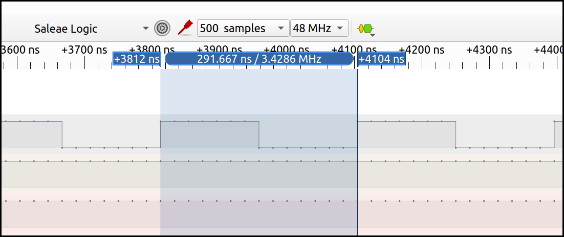
We can toggle the output at a frequency of more than 3 MHz. This concludes our hello world exercise.
A little refactoring: Extracting Subroutines
In the previous section, we have produced a good amount of code that’s often redundant and could be moved into a function. For instance, the code for setting the output pin is a such candidate. This serves as a preparation for the next sections so the code is easier to read and less error-prone.
The instruction set offers a special branch instruction ideal for implementing subroutines: BL (Branch with Link). When branching with link, the address of the next instruction (the return address) gets copied to the link register lr automatically so we know where to continue after returning from a subroutine.
The snippet below shows the principle: we jump to a label using bl, and return by setting the program counter pc to the value of lr).
.globl my_subroutine
my_subroutine:
	# [some code]
	mov pc, lr

bl my_subroutine
Passing arguments and returning values
In case we wanted to pass data into subroutines or return data, what would be the way to do that?
According to the ARM Developer Suite Assembler Guide (page 2-4), it looks like we’re free to use any of the available general-purpose registers, except for r13 (by convention used as the stack pointer, sp), r14 (link register lr), and r15 (program counter pc).
When interacting with other code or systems, it is probably wise to adhere to a certain Calling Convention which is part of an Application Binary Interface (ABI). ARM defines a Procedure Call Standard (AAPCS32) that specifies how arguments are passed and values are returned, e.g.:
The first four registers r0-r3 […] are used to pass argument values into a subroutine and to return a result value from a function. […] Typically, the registers r4-r8, r10 and r11 […] are used to hold the values of a routine’s local variables.
So, if we stick with r0 through r3 for passing and returning small amounts of data, this seems like a good rule to follow.
Subroutine for configuring output pin
The following snippet shows how to collect all the code for configuring the output pin in a subroutine. It does not make use of arguments or returning values; still, this can be a nice refactoring so the main program will read well (more on that later).
.globl configure_output
configure_output:
	# Prepare value for GPFSEL2:FSEL26 -> 0b001
	mov r0, #1
	lsl r0, r0, #18

	# Prepare target address
	ldr r1, =0x20200008

	# Store in memory
	str r0, [r1]

	# Return
	mov pc, lr
As a second example, let’s define a subroutine for setting an output pin. The following subroutine takes a gpio number in r0, and therefore provides some generalization (even though it is too simple to also cover GPIOs > 31).
.globl set_pin
set_pin:
	# This subroutine expects a GPIO # in r0
	# (note this only works for GPIOs 0...31)
	mov r1, #1
	lsl r1, r1, r0
	ldr r2, =0x2020001c
	str r1, [r2]
	mov pc, lr
Here’s how to call it for two different output pins:
mov r0, #26
bl set_pin

mov r0, #27
bl set_pin
The same can be done for clearing the output pin.
Outputting a proper serial frame
Toggling pins is a good exercise. For transmitting serial frames a receiver can understand, we need to respect timing.
A simple UART frame (8N1) consists of 1 start bit, 8 data bits, no parity bit, and 1 stop bit. Because there’s no clock shared between transmitter and receiver, the time each bit takes needs to be specified as the Baud Rate, e.g. 115,200 bit/s. This is where another peripheral comes into play: the System Timer (BCM2835 Datasheet, page 172).
The System Timer offers a free running 64-bit counter whose value can be read through two 32-bit registers (high and low). I couldn’t find the spot in the datasheet where its frequency is specified – but apparently, it is running at 1MHz. Let’s choose a baud rate we can easily achieve with sufficient accuracy: 1200 bit/s => 833 us.
Polling the timer
There are various ways of using this timer as a reference. Probably the simplest one suitable for this case is busy-waiting. Assuming we don’t expect our program to do anything else than transmit a frame, it is fair to just sit there and wait for 833 microseconds to expire. The following subroutine provides a microsecond delay we can use in our program.
.globl delay_us
delay_us:

# read System Timer CLO register
ldr r1, =0x20003004
ldr r2, [r1]

# calculate end time (expects microsecond delay in r0)
add r2, r2, r0

timer_loop:
ldr r3, [r1]

# end time reached?
cmp r3, r2
blt timer_loop

mov pc, lr
In this snippet, we’re using ldr to copy the content of a memory address into a register (see ARM memory access instructions vs. ARM pseudo-instructions). First, the address is loaded into r1 (pseudo instruction). Then, the value at this address is loaded into r2. You can tell the difference from the slightly different syntax.
We’re also introducing two new general data processing instructions: add, as the name suggests, is used to add a number of microseconds to the current timer count. cmp effectively calculates the difference r3 - r2 and updates associated status flags in the Current Program Status Register (CPSR) based on the result.
The subsequent branch instruction blt is a regular branch (b), combined with a less than condition code. It branches based on the state of the CPSR flags, in this case, based on the result of the cmp instruction.
Transmitting individual bits
Now comes the part where we send data out on the tx pin. There’s a subroutine for each possible state: high and low.
There are two new instructions in the code block below: push and pop. That way we make use of the stack to save the value of lr. These backups are needed for nested subroutine calls. Note this assumes the stack pointer (r13, sp) has been initialized properly (e.g. to 0x8000).
.globl uart_tx_high
uart_tx_high:
push {lr}
mov r0, #14
bl set_pin
ldr r0, =833
bl delay_us
pop {pc}

.globl uart_tx_low
uart_tx_low:
push {lr}
mov r0, #14
bl clr_pin
ldr r0, =833
bl delay_us
mov r0, #14
bl set_pin # set high to be sure we go back to idle state
pop {pc}
Transmitting full frames (characters)
Below you see the code for transmitting a frame, bit by bit. We prepare a bitmask in r5 that is applied to the character to be sent (r0) on every iteration of a loop. Depending on each bit’s state, either uart_tx_low or uart_tx_high is called.
One thing worth noting is the ands instruction. This is a bitwise AND that also updates the CPSR as a result. In contrast, a pure and instruction would not update CPSR. The s suffix is available for many instructions. In this case, the suffix is what we need to decide whether the result of the operation was zero or not.
.globl uart_tx_char
uart_tx_char:

push {lr} // Keep backup of LR because of function calls

// r0: Number/char to be transmitted
mov r4, r0
mov r5, #0x01 // Bit mask

# Bit 0: Start bit
bl uart_tx_low

tx_bit:
	ands r6, r4, r5 // Apply bit mask
	beq low // if result is zero
	bl uart_tx_high
	b end
	low:
		bl uart_tx_low
	end:

# End if 8 bits done
cmp r5, #0x80
beq after_tx

# Shift mask by one bit
lsl r5, r5, #1
b tx_bit

after_tx:

# Bit 9: Stop bit
bl uart_tx_high

pop {pc}
Putting it all together
Here’s the last step, the main program for transmitting three different characters in a loop.
mov r0, #14
bl set_pin

loop:

mov r0, #0x55 // U
bl uart_tx_char

mov r0, #0x56 // V
bl uart_tx_char

mov r0, #0x57 // W
bl uart_tx_char

b loop
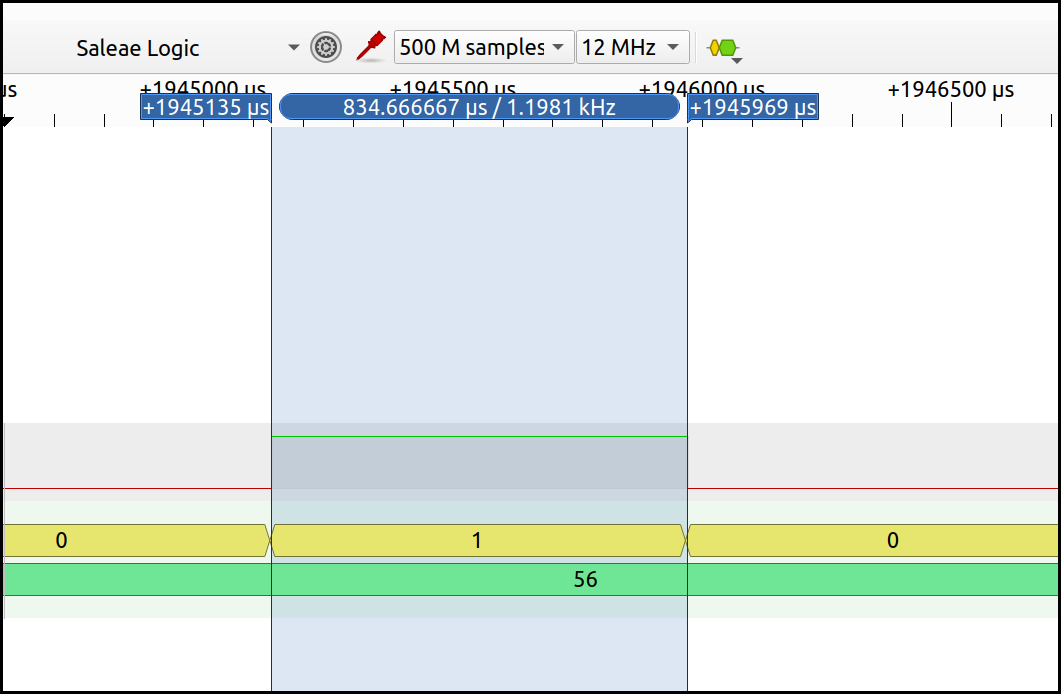
Output:
$ stty -F /dev/ttyUSB0 1200
$ cat /dev/ttyUSB0
UVWUVWUVWUVWUVWUVWUVWUVWUVW^C
Resulting logic analyzer screen:
Summary, References
This concludes this exercise of implementing a software UART transmission in ARM assembly. I hope you learned a few things on the way – for sure I did.
Below is a list of documents and tutorials you might find useful when diving more into this.
ARM
- ARM Developer Suite Assembler Guide (PDF, html)
- ARM1176JZF-S Technical Reference Manual
- ARMv5 Architecture Reference Manual (contains ARMv6 as well)
- ARM Architecture Reference Manual ARMv7-A and ARMv7-R edition
Raspberry Pi
Tutorials
- Baking Pi course by Alex Chadwick (University of Cambridge)
- explains well how to install the gnu toolchain
- David Welch: Raspberry Pi Bare-metal examples
- this is where I got the serial bootloader from.
- ARM-Asm Tutorial focussing on STM32
- Azeria Labs: ARM Assembly Basics
-
Use the command
arm-none-eabi-ld --verboseto show the internal linker script. ↩ -
There is a great explanation on the Pi’s boot sequence in David Welch’s raspberrypi-zero repo. ↩
-
The datasheet is just a partial one but I fear that’s all we’ve got. Also, be sure to check the errata page. ↩
-
For details on instructions, see chapter ARM Instruction Reference in the ARM Developer Suite Assembler Guide. ↩