In this episode of the series we are going to focus a bit more on the target hardware. The driver code created during the previous two episodes is going to be compiled for the target microcontroller and programmed into flash memory. While it's only the reset functionality of the MCP2515 we can verify right now, I think it's a step into the right direction.
SPIDriver for ATmega32
Let's begin by creating a simple SPIDriver implementation that interfaces with the actual peripheral of the ATmega32 microcontroller (uC). In the datasheet, all steps for transmitting and receiving single bytes via the SPI peripheral are described. There's even example code in C and assembler (page 134). Based on that information, we can create an implementation of the SpiDriver and put all the necessary code in there. The following code listing shows the definition of all the methods:
AvrSpiDriver::AvrSpiDriver() {
    SPI_DDR |= (1<<SS_DD) | (1<<MOSI_DD)
            | (1<<SCK_DD);
    SPI_DDR &= ~(1<<MISO_DD);
    SPCR =	(1<<SPE) |		// Enable
    		(1<<MSTR) |		// Master
    		(1<<SPR0);		// Clock rate
}

void AvrSpiDriver::select() {
    SPI_PORT &= ~(1<<SS_P);
}

void AvrSpiDriver::deselect() {
    SPI_PORT |= (1<<SS_P);
}

uint8_t AvrSpiDriver::read() {
    SPDR = 0x00;
    while(!(SPSR & (1<<SPIF)))
        ;
    return SPDR;
}

void AvrSpiDriver::write(uint8_t value) {
    SPDR = value;
    while(!(SPSR & (1<<SPIF)))
        ;
}
In the constructor, the SPI peripheral is configured as bus master and enabled. The selection and deselection of the slave is done via a normal GPIO pin (SS_P). Reading and writing is done in the simplest way possible - without using interrupts.
Integration & Test
An AvrSpiDriver instance can be passed on to the Mcp2515Core (remember? the one created using TDD):
AvrSpiDriver spiDriver;
Mcp2515Core<avrspidriver> mcpCore{spiDriver};
In order to issue the reset command via SPI, we call the corresponding method:
mcpCore.reset();
This yields the following output on the MOSI and CLK lines:
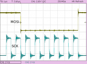
In the picture you can see the actual RESET instruction 0xC0 transmitted via the MOSI line.
The second oscilloscope screen shows the slave selection. The SPI slave is selected for (more than) the entire transmission period. Note that the time base has been changed between the two recordings.
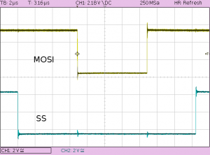
What we also see from the pictures is the clock polarity and phase. The SCK line is low when idle which is defined as clock polarity 0. Data is sampled on the rising edge of SCK. That means clock phase 0. These settings have been configured in the constructor of AvrSpiDriver. According to its datasheet, the MCP2515 supports this mode (specified as 0,0) and also mode 1,1.
Conclusion
Of course, this is a very simple example. Anyway, we've set the basis for further development on the Mcp2515Core class. Ideally, we can now focus on the TDD cycle for a long time without having concerns about whether our code still works on the actual hardware. As long as the specification of the SPIDriver interface is sufficient, everything else can be verified without having to upload anything to the target board.
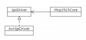
The following class diagram shows the new implementation in context:
As always, please let me know what you think about this article via twitter @ronalterde!
Example Project
If you'd like to reproduce the above steps, you can download a make-based example project from github.com/ronalterde/mcp-tdd-part3. You can run that demo on your own AVR board. An MCP2515 is still not really necessary.
The example is prepared for use with an ATmega32 together with an USBtiny programmer but probably can be adjusted to suit the needs of your target hardware.